STM32 Project Consulting: Discovery

Pages

Affichage des articles dont le libellé est Discovery. Afficher tous les articles

STM32F4 Discovery USART example

Upon request I’m posting this USART example code for the STM32F4 which initializes USART2 and constantly sends the character ‘h’.


#include <stm32f4xx.h>
#include <stm32f4xx_usart.h>

void init_usart(void){

 GPIO_InitTypeDef GPIO_InitStructure;
 USART_InitTypeDef USART_InitStructure;

 /* enable peripheral clock for USART2 */
 RCC_APB1PeriphClockCmd(RCC_APB1Periph_USART2, ENABLE);


 /* GPIOA clock enable */
 RCC_AHB1PeriphClockCmd(RCC_AHB1Periph_GPIOA, ENABLE);

 /* GPIOA Configuration:  USART2 TX on PA2 */
 GPIO_InitStructure.GPIO_Pin = GPIO_Pin_2;
 GPIO_InitStructure.GPIO_Mode = GPIO_Mode_AF;
 GPIO_InitStructure.GPIO_Speed = GPIO_Speed_50MHz;
 GPIO_InitStructure.GPIO_OType = GPIO_OType_PP;
 GPIO_InitStructure.GPIO_PuPd = GPIO_PuPd_UP ;
 GPIO_Init(GPIOA, &GPIO_InitStructure);

 /* Connect USART2 pins to AF2 */
 // TX = PA2
 GPIO_PinAFConfig(GPIOA, GPIO_PinSource2, GPIO_AF_USART2);

 USART_InitStructure.USART_BaudRate = 9600;
 USART_InitStructure.USART_WordLength = USART_WordLength_8b;
 USART_InitStructure.USART_StopBits = USART_StopBits_1;
 USART_InitStructure.USART_Parity = USART_Parity_No;
 USART_InitStructure.USART_HardwareFlowControl = USART_HardwareFlowControl_None;
 USART_InitStructure.USART_Mode = USART_Mode_Tx;
 USART_Init(USART2, &USART_InitStructure);

 USART_Cmd(USART2, ENABLE); // enable USART2

}

void Delay(__IO uint32_t nCount)
{
  while(nCount--)
  {
  }
}

int main(void){

 init_usart();

 uart_puts("Init complete!");

 while(1){
  USART_SendData(USART2, 'h'); // defined in stm32f4xx_usart.h
  Delay(0x3FFFFF);
 }

}
 
 
I hope that is helpful . 
 

STM32F4 Discovery USB host and MP3 player

I have not written any new post for a while, so here is one more project for the stm32f4 discovery. I prepared this post a long time ago, but for some reason I never posted it, so here goes:


Based on one of the examples provided by ST, I have written a program for the STM32F4 Discovery board that plays MP3 files from an USB memory stick. You can download it

If you use a usb-host cable such as this one you can connect an USB memory stick (with fat32 file system) with mp3-files to the micro-usb port of the stm32f4 discovery. The files should then be played one by one. The user button can be used to skip to the next file.
If you follow this tutorial you should be able to build and upload the provided files right away.
The main.c-file has many comments, so hopefully you can figure out how it works. Using a USB-memorystick for logging is quite easy with this program as a basis. Only the two usb-pins, 5V and gnd are required to connect it to any stm32 with USB support, so hw-wise it’s even easier than using an SD-card.

STM32F4 Discovery and ULINK2

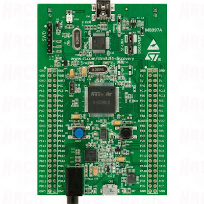
On-board is a STM32F407VGT6 microcontroller. On Board is an ST-LINK/V2 embedded debug tool, two ST MEMS, digital accelerometer and digital microphone, one audio DAC with integrated class D speaker driver, LEDs and push buttons and an USB OTG micro-AB connector. By removing two jumpers ST-LINK could be used to program external microcontroller.


ST-Link V2 is intended for debuging the on-board microcontroller or as debug interface for any external ST cortex MCU. I have ULINK2 Debug Adapter. and I wanted to connect discovery board to ST32F4 MCU.  Unfortunately there’s no direct debug connection to DISCOVERY board, which could allow using external debugging interfaces. Here’s how it can be done:
Take STM32F4-DISCOVERY board and turn it upside down. There are several jumpers (solder bridges) marked with SBxxx. Remove SB5 and SB9. This will disconnect ST/LINK output signals from main MCU avoiding colision with ULINK2 signals:

Next, solder tiny wires to open solder bridges. Each solder bridge has arrow shape. Connect wires at proper side of the jumpers and to pads, as indicated in this diagram:


Next, solder breadboard with 20 pin header to discovery board and connect wires to proper pins as indicated above. Take care about IDC pin numbering (zig-zag)!
Connect ULINK-2, run uVision, open your favorite STM32F400 project and check the debug window:


And finally, snapshot with webcam (I was holding my DELL above the desk):