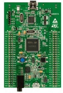
ST Micro Electronics promotion boards popularly known as Discovery boards are available in variety of versions with each version enables you exploring a different member to ST’s Micro controller Family. STM32F4 Discovery board is one of those boards which let you explore the features and methods of STM32F4xx series of Controllers.
Features of STM32F4 Discovery Board
- STM32F407VGT6 microcontroller featuring 1 MB of Flash memory, 192 KB of RAM in an LQFP100 package
- On-board ST-LINK/V2 with selection mode switch to use the kit as a standalone ST-LINK/V2 (with SWD connector for programming and debugging)
- Board power supply: through USB bus or from an external 5V supply voltage
- External application power supply: 3V and 5V
- LIS302DL, ST MEMS motion sensor, 3-axis digital output accelerometer
- MP45DT02, ST MEMS audio sensor, omnidirectional digital microphone
- Eight LEDs:
– LD1 (red/green) for USB communication
– LD2 (red) for 3.3V power on
– Four user LEDs, LD3 (orange), LD4 (green), LD5 (red) and LD6 (blue)
– 2 USB OTG LEDs LD7 (green) VBus and LD8 (red) over-current - Two pushbuttons (user and reset)
- USB OTG with micro-AB connector
- Extension header for LQFP100 I/Os for quick connection to prototyping board and easy
probing
Understanding Development
he board comes mounted with STM32F407VG Microcontroller chip on it, with a huge 100 Pin package. Along with Micro controller at the heart of the system, this board has some interesting peripheral to work with.
STM32F4xx Series of MCU are based on ARM Cortex M4 core, To work with cores like this, you need to have some third party libraries, that is the only way to utilize its full features. Simple reason behind this is that, these cores are feature rich and many different vendors uses these cores in their devices, so to achieve a common standard some Hardware Abstraction layers are needed. Like in this case we will be using CMSIS Library where CMSIS stands for Cortex Microcontroller Software Interface Standard.
he ARM® Cortex™ Microcontroller Software Interface Standard (CMSIS) is a vendor-independent hardware abstraction layer for the Cortex-M processor series. The CMSIS enables consistent and simple software interfaces to the processor and the peripherals, simplifying software re-use, reducing the learning curve for new microcontroller developers and reducing the time to market for new devices.
So, as it is clear CMSIS is standard HAL for all devices using ARM CORTEX as CPU core. CMSIS helps you utilize core features like DSP co-processor, Floating Point Unit etc in an easier way. So CMSIS is for CORE Features, Now lets discuss things outside the CPU core, Each vendor (ST in this case) uses CORTEX core and makes their own ARM based devices by adding some additional features/ peripherals around core. For example almost all vendors add peripherals like USART, ADC, I2C, SPI, CAN, Timers etc. These peripherals too need drivers or Hardware Abstraction Layer, I am not saying that it is impossible to write Drivers for specific peripheral inside MCU, but it consumes your development time. So in order to simplify the development process specific vendors (ST in our case) provide some peripheral driver library. ST Micro Electronics has provided a rich set of peripheral driver firmwares, so that you can quickly move onto applications without worrying about each bit of register level details.
So, from above discussion it is clear that we are going to use these two libraries…
- CMSIS (Cortex Microcontroller Software Interface Standard)
- STM32F4 Firmware Library / Standard Peripheral Drivers
Application Development
Now, having all third party (CMSIS) / vendor specific (ST Micro) software library support with us, Lets get right onto application development.
Downloads :
1- Download the STM32F4 Firmware Library From STMicroelectronis site .
2- STM32F4 Discovery Board Reference Manual + Datasheet
3- For user : The STM32F4 User Manual
Required Software :
1- IDE to developp application on STM32F4 like :
* IAR Embedded WorkBench
* Keil µVision
* Atollic TrueStudio
2- Debugger (That IDE like IAR Embedde WorkBench Debug Application on Board )
3- ST Link Software (it included on Board )
Understanding STM32F4 Firmware Library :
I hope, you have downloaded the FW library from the Link given above, Extract it somewhere in your computer. You will find directory organization something like shown below…

Libraries folder contains CMSIS, STM32 USB Device Library, STM32 USB Host Library, STM32 USB OTG Driver, STM32F4xx _StdPeriph_Driver. Here CMSIS is the library dealing with core specific features and other libraries deal with STM32 family’s specific peripheral feature.
Project folder contains example projects for some of the peripherals of MCU. Each example project is configured for 4 different development platforms like Keil MDK, IAR EW etc. WE are going to use Keil MDK. These example project are greatest help for any newbie, so read some of these attentively, we are going to analyse the standard IO_Toggle example here in this post itself.
Utilities folder has some codes specific to STM32F4 Discovery board like LED’s, Button’s macro definitions. Most of it is very easy to understand just give it a try.
Lets Analyse our First application on STM32F4 Discovery Board :
Best way to make an initial understanding of the working of STM32F4xx is to mess around with the example projects provided by ST as a board support package. Go to the folder where you extracted the Firmware package. Now move inside Project->Peripheral_Examples->IO_Toggle. Open readme file and read about the purpose of this example project. readme file gives you a great deal of details about organization of any project. Now open up the main.c file, You should see the following C code in it.
#include "stm32f4_discovery.h"

GPIO_InitTypeDef  GPIO_InitStructure;

void Delay(__IO uint32_t nCount);
int main(void)
{

  /* GPIOD Periph clock enable */
  RCC_AHB1PeriphClockCmd(RCC_AHB1Periph_GPIOD, ENABLE);

  /* Configure PD12, PD13, PD14 and PD15 in output pushpull mode */
  GPIO_InitStructure.GPIO_Pin = GPIO_Pin_12 | GPIO_Pin_13| GPIO_Pin_14| GPIO_Pin_15;
  GPIO_InitStructure.GPIO_Mode = GPIO_Mode_OUT;
  GPIO_InitStructure.GPIO_OType = GPIO_OType_PP;
  GPIO_InitStructure.GPIO_Speed = GPIO_Speed_100MHz;
  GPIO_InitStructure.GPIO_PuPd = GPIO_PuPd_NOPULL;
  GPIO_Init(GPIOD, &GPIO_InitStructure);

  while (1)
  {
    /* PD12 to be toggled */
    GPIO_SetBits(GPIOD, GPIO_Pin_12);

    /* Insert delay */
    Delay(0x3FFFFF);

    /* PD13 to be toggled */
    GPIO_SetBits(GPIOD, GPIO_Pin_13);

    /* Insert delay */
    Delay(0x3FFFFF);

    /* PD14 to be toggled */
    GPIO_SetBits(GPIOD, GPIO_Pin_14);

    /* Insert delay */
    Delay(0x3FFFFF);

    /* PD15 to be toggled */
    GPIO_SetBits(GPIOD, GPIO_Pin_15);

    /* Insert delay */
    Delay(0x7FFFFF);

    GPIO_ResetBits(GPIOD, GPIO_Pin_12|GPIO_Pin_13|GPIO_Pin_14|GPIO_Pin_15);

    /* Insert delay */
    Delay(0xFFFFFF);
  }
}

void Delay(__IO uint32_t nCount)
{
  while(nCount--)
  {
  }
}
Above example program toggles each of 4 On board LEDs one by one and the interval between toggle sequence is determined by Delay() function. Let us try to understand how things go around in the above code.
Line 1 : Includes “stm32f4_discovery.h” file which defines the LED and Button connections for Discovery Board, this files has various STM32F4 Discovery board specific Macro definitions. You can find this file inside ‘Utilities\STM32F4-Discovery’.
Line 3: GPIO_InitTypeDef GPIO_InitStructure; This is something interesting, ST firmware library uses lots of these kind of structures, in fact for every peripheral of microcontroller, you will find one such structure definition. The simple reason behind such structures is that each peripheral has a set of parameters, which programmer has to configure in order to achieve proper working of that peripheral. So instead of configuring each of the registers/parameter individually, Its better to make a structure of all parameters and whenever you need to configure that peripheral just declare an instance of that structure and assign proper values to each of the parameter as per your need.
Lets look what’s there inside GPIO_InitTypeDef…
typedef struct
{
  uint32_t GPIO_Pin;              /* Specifies the GPIO pins to be configured.
                                       This parameter can be any value of @ref GPIO_pins_define */

  GPIOMode_TypeDef GPIO_Mode;     /* Specifies the operating mode for the selected pins.
                                       This parameter can be a value of @ref GPIOMode_TypeDef */

  GPIOSpeed_TypeDef GPIO_Speed;   /* Specifies the speed for the selected pins.
                                       This parameter can be a value of @ref GPIOSpeed_TypeDef */

  GPIOOType_TypeDef GPIO_OType;   /* Specifies the operating output type for the selected pins.
                                       This parameter can be a value of @ref GPIOOType_TypeDef */

  GPIOPuPd_TypeDef GPIO_PuPd;     /* Specifies the operating Pull-up/Pull down for the selected pins.
                                       This parameter can be a value of @ref GPIOPuPd_TypeDef */
}GPIO_InitTypeDef;
As you can see, Structure for GPIO_InitTypeDef has properties like Pin number in a PORT, its MODE (Input/Output), Speed, Output Type (Open Drain etc.), PULL UP/DOWN configuration.
Line 13-17 : You initialize the GPIO properties as per your application requirements. Here we initialize Pin 12, 13, 14 and 15 of GPIOD as output so that we can toggle the LEDs attached to them.
Line 10: In STM32F4xx you need to initialize the clock to each of the peripheral before using that peripheral. That can be done using RCC (Reset and Clock Control). STM32F4xx has two kind of buses, AHB (Advance High Performance Bus) and APB (Advanced Peripheral Bus). Some of the peripherals are connected to AHB (Like GPIO) and some are connected to APB (like I2C). As we are using GPIO here we have used RCC function as “RCC_AHB1PeriphClockCmd”.
Rest of the code is pretty much self explanatory, If you feel any difficulty understanding the amount of abstraction used here, please leave a comment below.
Aucun commentaire:
Enregistrer un commentaire